Engineering & Buyer Guide
Trolley Locomotive Power Supply: A Design and Acceptance Checklist
What must be specified for an underground trolley locomotive power supply?
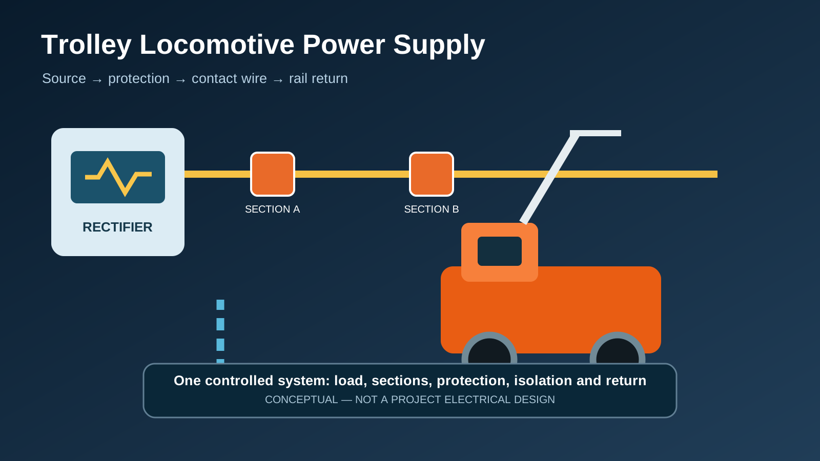
Conceptual one-line: source, protection, contact path and rail return must be engineered and accepted as one system.
TL;DR / Direct Answer
What must be specified for an underground trolley locomotive power supply?
A trolley locomotive power supply is a complete electrical and rail-return system, not only an overhead conductor and rectifier. Define locomotive demand and simultaneity, incoming supply, conversion, feeder and section arrangement, contact and return paths, protective devices, isolation boundaries, clearances, bonding, earthing, interfaces with people and equipment, maintenance access and acceptance tests. Apply the mine's current electrical rules and competent engineering; voltage or conductor values from another jurisdiction are not a project design.
Which inputs define the electrical design basis?
Begin with the approved fleet and operating plan. Record locomotive voltage range, continuous and peak demand, current-collection arrangement, regenerative or other braking interface where applicable, train cycles, simultaneous trains, starting locations, gradients, loading points, sidings and future expansion. Connect this duty to the capacity model rather than assuming every locomotive reaches peak demand at the same time or that a nameplate value represents route energy.
Survey the mine supply and physical route. Capture source capacity and fault information, cable and feeder distances, proposed rectifier locations, conductor coverage, section boundaries, rail and joint construction, return-current path, wet or corrosive areas, clearances, doors, crossings, work zones, explosives restrictions and emergency access. Record the authority having jurisdiction and the controlled standards list. The design must show which requirements are statutory, mine rules, manufacturer limits or project choices.
| Input group | Minimum decision | Evidence owner |
|---|---|---|
| Fleet and duty | Locomotives, demand states, simultaneity and growth | Mine planning and supplier data |
| Source | Supply capacity, conversion, fault level and power quality | Mine electrical engineer |
| Route | Coverage, sections, clearances, crossings and work interfaces | Survey and route design |
| Return | Rail conductivity, bonds, earthing and stray-current review | Electrical and track design |
| Protection | Fault detection, interruption, isolation and coordination | Approved protection study |
How should the supply architecture be divided?
Develop a controlled one-line from the mine supply through transformer or conversion equipment, rectifier where used, DC switchgear, feeders, sectionalizing devices, contact conductor, locomotive collector, wheels, rails and return connections. Identify normal open points, parallel feeds, branch lines and any non-trolley gaps. Every isolator and protective device needs a unique tag that matches drawings, labels, procedures and maintenance records.
Sectioning should support fault limitation, maintenance and operational recovery without creating ambiguous backfeed. Define the maximum area lost for a credible fault and how a train is recovered from a dead section. Model voltage at demanding locations under agreed duty scenarios and verify equipment limits, conductor heating and return performance. Calculations require project values; this guide intentionally supplies no universal voltage-drop or conductor-size limit.
- Freeze the fleet duty and route coverage assumptions.
- Build the source-to-rail-return one-line with tagged boundaries.
- Study load flow, fault conditions, protection and credible backfeed.
- Check physical clearances, access, collector transitions and work zones.
- Define isolation, recovery, inspection and acceptance evidence.
Why must the contact wire and rail return be designed together?
Current reaches the locomotive through the contact system and returns through wheels, rails, joints, bonds and designated connections. Poor continuity can create voltage loss, heating, unreliable protection behavior and unwanted current paths. HSE underground track guidance specifically tells designers of electric trolley-locomotive track to consider conductivity, earthing and bonding of rail joints in its UK context. Treat track work and electrical work as one controlled interface.
Specify conductor support, alignment and transitions for the approved collector geometry and vehicle movement. Include switches, curves, crossings, loading stations, maintenance areas and route irregularities. Define inspection points and permissible wear or misalignment from approved project documentation. The return-path design should consider other metallic services and site corrosion concerns; competent electrical assessment is required rather than a generic bonding recipe.
What protection and isolation questions must be closed?
The protection study should define faults to detect, device ratings, interrupting capability, selectivity, reach at remote line ends, automatic reclosing policy, grounded-phase or return-path behavior where relevant, indication, testing and change control. In the United States underground-coal context, published CFR provisions address trolley circuit interruption and guarding. MSHA's electrical inspection handbook discusses representative circuit-breaker testing. These are jurisdiction-specific evidence prompts, not settings for another mine.
Provide visible, lockable isolation with an approved method for proving de-energized condition and controlling stored or backfed energy. State who may isolate, test, earth where required and release the system. Include emergency switching from accessible locations and communications between the dispatcher, electrical controller and work party. A tripped breaker must not be reclosed until the approved fault and route checks are complete.
Engineering note: Electrical safety boundary: all ratings, settings, clearances and test levels require project calculations, equipment data, mine rules and approval by competent persons. This article is not an energized-work procedure.
How should clearances and non-routine movements be managed?
Survey the envelope of locomotives, cars, loads, people and maintenance equipment against the energized conductor and supports. Consider raised loads, long material, derailment displacement, track maintenance tools, water management, doors and temporary construction. Guard and isolate at locations where people work or pass as required by the applicable design. Signage alone may not control a foreseeable contact where physical or electrical protection is practicable.
Create a separate plan for moving off-track or oversized equipment along the trolley route. Current US CFR text provides a specific coal-mine example involving examination, supervision, guarding, communication and circuit protection; it cannot be copied as a universal procedure. The 2025 MSHA proposed rule to remove trolley references because of stated US usage conditions is an important freshness signal: trolley practice and regulation vary materially by market, so every international project must verify current local requirements.
What operating and maintenance controls are needed?
Create identified inspection routes for rectifiers, switchgear, feeders, section devices, supports, contact wire, collectors, rails, bonds and return connections. Define condition measures, approved limits, inspection frequency, access protection, defect classes and responsibility from manufacturer information, engineering assessment and mine rules. Coordinate with track maintenance because rail-joint or replacement work can alter the electrical return path.
Maintain controlled settings, drawings, test reports and spare-device data. Record breaker operations, earth or return alarms, hot connections, collector damage, repeated section trips and voltage complaints by location and operating state. Trend causes rather than resetting equipment until it runs. Any fleet, voltage, feeder, track or route change should trigger a documented review of load, fault, protection, clearance and return-path assumptions.
| Asset | Condition evidence | Change trigger |
|---|---|---|
| Rectifier/switchgear | Ratings, settings, tests, alarms and trip history | Source, load or protection change |
| Feeder/contact system | Connections, support, alignment, wear and insulation | Route, collector or section change |
| Rail return | Bond continuity, joints, connections and observed heating | Rail replacement or track work |
| Isolation | Tags, locks, indication, procedures and drills | New work boundary or backfeed path |
| Documents | Current one-line, route map and controlled settings | Any approved configuration revision |
What should FAT and site acceptance verify?
Factory evidence should verify supplied equipment identity, ratings, construction, protection functions, controls, indications, communications interfaces, settings governance and document completeness to the agreed scope. Site checks should verify installation against drawings, conductor and support condition, tagged section boundaries, clearances, rail-return and bonding evidence, isolation, protection injection or functional tests, alarm routes and safe energization steps under the approved method.
Operational proving should cover representative locomotive starts and runs at defined locations, section transitions, simultaneous demand cases, voltage and current evidence, collection behavior, normal switching and controlled fault or loss-of-section responses. Keep traction performance, electrical acceptance and production capacity as linked but separate acceptance records. Record environment, configuration, instruments, expected results, deviations and authorization for every test.
What should a trolley-power RFQ contain?
Supply the route survey, fleet and duty schedule, locomotive electrical data, source information, existing one-line and track construction, environmental classification, communications and control interfaces, applicable standards, scope boundaries and expansion case. Ask bidders to return calculations, equipment schedules, conductor and rail-return design, protection philosophy, section and isolation plan, civil/installation loads, exclusions, FAT/SAT and maintenance deliverables.
Commercial comparison should include transformer or converter scope, rectification, switchgear, feeder and contact hardware, rail bonds, monitoring, spares, tools, installation supervision, training, commissioning and document updates. Require a responsibility matrix for mine, electrical contractor, track contractor and locomotive supplier. ShaoLi can review locomotive and control interfaces against supplied project data; the mine's appointed designers and authorities remain responsible for the electrical installation and approval.
- Fleet load, simultaneity and route coverage schedule.
- Source, one-line, fault and protection input pack.
- Contact, section, clearance and rail-return requirements.
- Isolation, maintenance and degraded-operation concept.
- FAT, installation, SAT, proving and handover evidence matrix.
Frequently asked questions
How does a trolley mining locomotive receive power?
The locomotive collects electrical power from a contact conductor; current passes through onboard controls and traction equipment and returns through the wheels, rails, bonds and designated return connections.
What voltage should an underground trolley locomotive use?
There is no universal value. Match the locomotive, duty, route length, source, fault protection, conductor and return path to applicable rules and project calculations.
Why is the rail part of the electrical design?
In common trolley arrangements the rails form the return path. Joint conductivity, bonding, earthing interfaces, track work and unwanted current paths therefore affect electrical performance and protection.
How should a trolley line be divided into sections?
Section boundaries should support fault limitation, isolation, maintenance and recovery while preventing backfeed. Their locations follow the surveyed route, loads, switches, branches and approved operating plan.
Can a trolley circuit breaker simply be reset after a trip?
No. Follow the approved mine procedure: establish the fault and route condition, inspect as required, obtain authorization and re-energize only when the defined evidence is complete.
What changes require the trolley system to be reassessed?
Review fleet size, locomotive type, voltage, route extension, feeder or section changes, track replacement, collector changes, protection settings and new equipment movements near conductors.
What should site acceptance measure?
Verify installation and tags, protection, isolation, clearances, contact and rail return, alarms and representative operating states against approved project criteria with traceable instruments and records.
Sources & references
- HSE Rail track and associated equipment for use underground in mines
UK guidance used for electric-trolley track conductivity, earthing and rail-joint bonding prompts; it is not a universal electrical design.
- US 30 CFR Part 75 (2025 edition)
Official US underground-coal provisions used as a jurisdiction-specific example for trolley protection, guarding and equipment movements.
- MSHA Coal Mine Electrical Inspection Procedures
Historical US inspection handbook used for protection-testing and documentation questions, not transferable settings.
- MSHA 2025 proposed rule on obsolete trolley provisions
Current US regulatory signal showing that trolley usage and rules vary by jurisdiction; the proposal is not a final rule or a global technology conclusion.
- HSE introduction to electrical safety
General UK electrical-safety context for competence and work near overhead conductors; mine-specific rules remain controlling.
Turn the guide into a project requirement
Send the route, train, duty, power, environment and interface data. ShaoLi can review the requirement against relevant product and solution paths without treating a generic guide as a final design.
Request an engineering review